
Application
1,For connection of polymeric cable to transformers, switchgear, motors and other equipment with a premoulded separable connector.
2,For indoor and outdoor installations.
3,System voltage up t0 24 kV.
4,Continuous cu rrent 630A(900 A ove rload for 8 hours).
5,Cable particulars:
a,Polymeric cable(XLPE,EPR, etc.).
b,Copper or aluminum conductors.
c,Semiconducting or metallic screens.
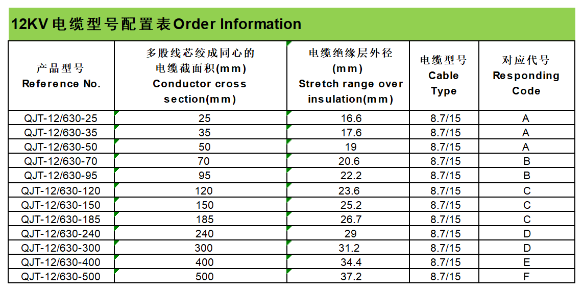
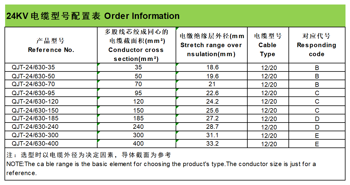
d,Conductor size12kV25-120mm 24kV25-400mm.
Features
1,Provides a fully screened and fully submersible separable connection when mated with the proper bushing or plug.
2,Can be used under the circumstances.
3,Built-in capacitive test point to determine the circuit status or installation fault indicator.
4,No minimum phase clearance requirements.
5,Mounting can be vertical, horizontal, or any angle in between.
Installation
1,Without any special tools.
2,When finish the installation of elbow connector, the power can be supply directly.
3,According to the Installation Instruction Sheet.
4,Any other special requirement , please contact our sales engineer.
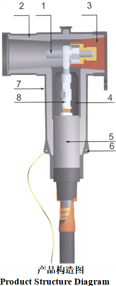
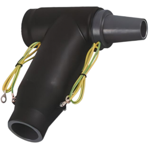
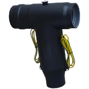
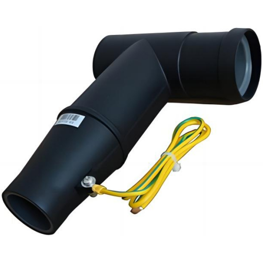
Product Structure
- TWO HEAD SCREW: To make sure have a good contact with the apparatus bushing.
- INSULATION: Moulded EPDM insulating rubber is formulated and mixed in-house to ensu re hig h q uality.
- INSULATING PLUG: Molded epoxy insulating plug provides excellent electrical, thermal and mechanical reliability.
- SEMI-CONDUCTIVE INSERT: Moulded EPDM conducting rubberscreen controls electrical stress.
- STRESS RELIEF: The configu ration of the outer screen and the cable adapter provide ca ble stress relief.
- GROUNDING EYE: Moulded into the externalscreen forconnection ofan earthing wire.
- SEMI-CONDUCTIVE SHIELD: Moulded EPDM conducting rubber mates with the cable screen to maintain screen
continuity and ensure that the assembly is at earth potential.
- CONDUCTOR CABLE LUG: Aluminum compression connectoris sized to ensure a cool running connector with maximum
current transfer.
European Touchable Series Cable Connector Installation Instructions
Product Description
This series of cable joints is a European-style touchable series cable joint, which is fully insulated, fully shielded and waterproof. The material is imported silicone rubber, using the internationally advanced full-injection three-layer composite molding process. It is suitable for ring main units, cable branch boxes, and box-type substations that meet DIN47636 standards and have a rated current of 630A. It can be connected to voltage levels of 15KV and below, and the insulation diameter is 16-35mm (25-400) XLPE cable.
Touchable front connector product components: touchable front connector body, stress cone, crimp terminal, buckle, insulating plug, end cover, M16/12 reducing bolt, nut, flat washer, elastic washer, lubricating silicone grease, grounding wire , cleaning wipes.
Touchable rear connector product components: touchable rear connector body, stress cone, crimp terminal, buckle, conductive rod, M12 bolt, lubricating silicone grease, grounding wire, cleaning towel,Back-connected arrester product components: back-connected arrester body, conductive rod, M12 bolt, lubricating silicone grease, grounding wire, cleaning towel.
Installation tools: socket wrench, adjustable wrench.
Installation Steps
- Three-core cable phase separation processing:
1.1 , Place the cable vertically and conduct phase separation 1.0-1.5m away from the cable terminal. Cut off the outer sheath and steel armor belt in this section. Then peel off 30mm of the outer sheathing downwards, leaving 10mm of the inner sheathing upwards, and peel off the excess inner sheathing and filler. Pay attention to the separate grounding of the copper shielding tape and steel armor.
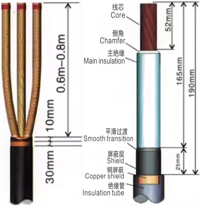
- Single-core cable processing:
- , Cable copper shielding treatment: Place the cable vertically, measure 190mm downward from the top of the cable, peel off the outer sheath and copper shielding tape of the cable, and expose the cable shielding layer.
- , Cable shielding layer treatment: Measure 165mm from the top of the cable downward, and neatly peel off the cable shielding layer. Remember not to cause any damage to the main insulation layer of the cable when peeling off the shielding layer! And do this at the transition between the insulation layer and the shielding layer. Smooth chamfers to ensure smooth transitions. This operation is an important step to ensure smooth operation of the cable!
- , Cable insulation layer treatment: Measure 52mm downward from the top of the cable, peel off the cable insulation layer, and expose the cable core. Then make a smooth chamfer about 3mm from the top of the insulation layer to avoid scratches when the stress cone is installed.
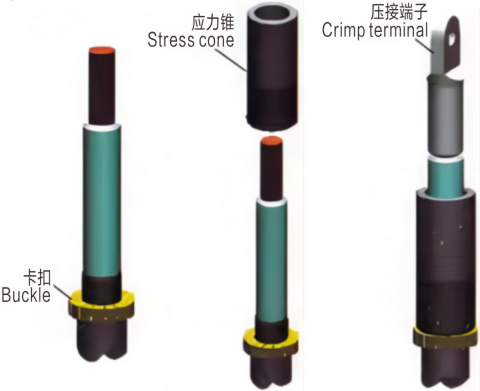
- Install the stress cone and crimp terminal:
3.1, Install the buckle: Wrap the buckle around the lower end of the cable shield, close to the copper shield (the upper end of the insulation tube), and then lock it.
The buckle has three colors of red, yellow and green that are separated by the cable phase.
3.2, Install the stress cone: Clean the surface of the insulation layer and the inner surface of the stress cone, and evenly apply silicone grease. Then insert the stress cone from the wire core and push it down until the lower surface is flat against the buckle.
Note: The stress cone cannot be set backwards, with the black part facing downwards.
3.3, Install the crimp terminal: Insert the crimp terminal into the wire core, and rotate the direction of the terminal until the terminal head plane is parallel to the end face of the sleeve. Press the terminal downwards from the terminal head position according to the crimp mark on the terminal. (Confining pressure is recommended). After the crimping is completed, the sharp edges formed during crimping should be smoothed with a file and cleaned. Note: It is required to use crimp terminals with the same specifications as the cables. Use copper terminals for copper core cables and copper-aluminum transition terminals for aluminum core cables.
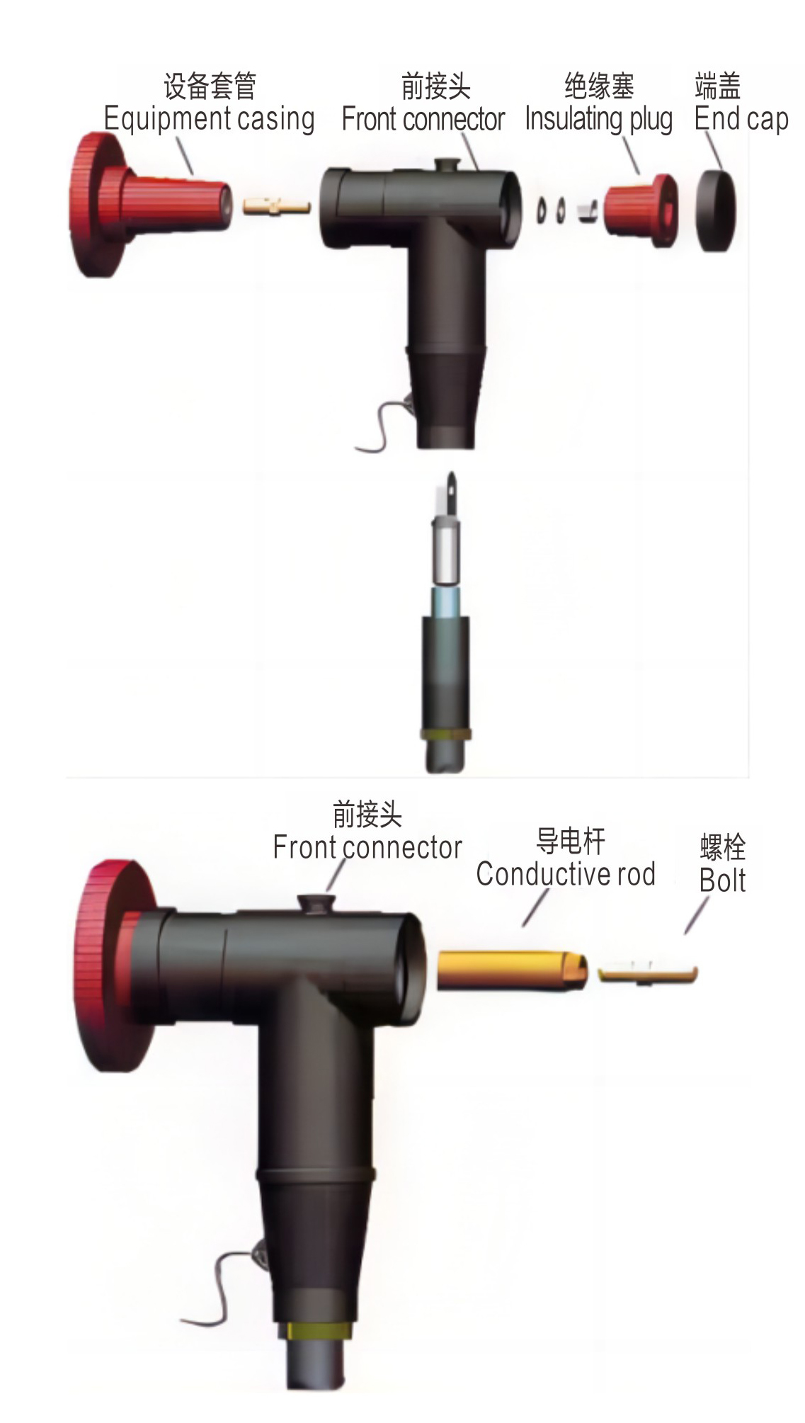
- Install European-style touchable front connector:
4.1, Check the screw hole of the equipment casing (the standard thread is M16, if not, please notify the company in time to make corresponding changes), screw the M16/12 reducing bolt into the screw hole of the casing and tighten it. The depth of bolt screwing into the casing should be a minimum of 25mm.
4.2, Clean the equipment sleeve, front connector, crimp terminal, stress cone, insulation plug and end cover, and evenly apply silicone grease on the outer surface of the stress cone, the inner surface of the front connector, the outer surface of the equipment sleeve, and the outer surface of the insulation plug.
4.3, Put the cable with crimped terminals into the front connector until the hole on the upper part of the terminal is at the center of the front connector.
4.4, Put the front connector into the equipment casing, and the reducing bolt should pass through the round hole of the crimp terminal.
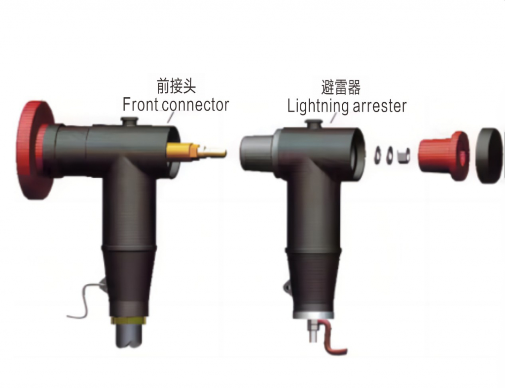
4.5, If you want to install a rear connector or lightning arrester later, please go to installation step 5.
4.6, Place the flat washer, spring washer and nut on the bolt in sequence, tighten the nut with a socket wrench, then put on the insulating plug and cover the end cover.
4.7, Check the tightness of the ground wire on the front connector body. If it is loose, please tighten it. Make a good connection to the system ground on the other end of the ground wire.
4.8, Check all connections and confirm that they are in place. The touchable front connector is installed.
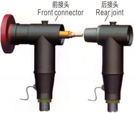
- Install touchable rear connector:
5.1, Use a wrench to tighten the conductive rod on the bolt in the front joint to ensure that the conductive rod is the pole makes good contact with the front connector crimp terminal. Then tighten the M12 bolts.
5.2, Push in the cable with terminals processed according to steps 1, 2 and 3.
Connector until the hole in the upper part of the terminal is in the center of the rear connector.
5.3, Align the rear connector of the installed cable with the front connector and insert it. Guaranteed conductive rod is flush with the terminal surface of the rear connector, and the bolt passes through the round hole of the rear connector terminal.
5.4, If expansion is needed, follow the same method to install the rear joint or
lightning arrester.
5.5, If no expansion is required, follow the installation sequence 4.6-4.8 in step 4. to Install the rear connector.
- Install rear-mounted lightning arrester:
6.1. Clean the outer surface of the arrester and evenly apply lubricating silicone grease.
6.2, repeat steps 5.1.
6.3. Align the arrester with the front connector (or rear connector) and insert it.
6.4. Repeat steps 4.6-4.8 of step 4 to connect the insulation plug and end cap.
6.5, Tighten the ground wire to the system ground point.
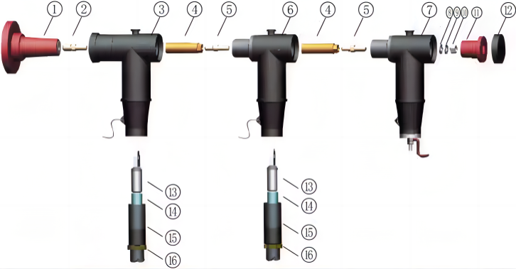
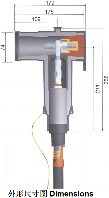
1, 设备标准套管. Equipment standard casing.
2, M16螺栓. M16 Bolt.
3, 前接头. Front connector.
4, 导电杆. Conductive rod.
5, M16螺栓. M16 Bolt.
6, 后接头. Rear connector.
7, 后接避雷器. Rear lightning arrester.
8, 平垫. Flat pad.
9, 弹垫. Spring pad.
10, 螺母. Nut.
11, 绝缘塞. Insulating plug.
12, 后端盖. Rear end cover.
13, 压接端子. Crimp terminal.
14, XLPE电缆. XLPE Cable.
15, 应力锥. Stress cone.
16, 卡扣. Buckle.
◆Special Customization
The above parameters are typical data; if the existing styles do not meet your specific demands, please contact us for a custom design.We have significant personalized customization development and production skills, allowing us to provide tailored solutions to customers all over the world.