

General Information
The 24kV SF6 gas insulated metal fully enclosed and fully insulated series ring network switch cabinets produced by the company are widely used in 12kV power distribution systems and are the preferred switch products for power transformation and distribution systems for various urban and rural users.
The switch cabinet is a modular unit model that can be combined according to different uses; it is divided into two categories: fixed unit combinations and expandable units to meet the needs of various substations for flexible use of compact switch cabinets.
The 24kV GIS switch cabinet is a completely sealed system, with its electrical components and switches enclosed in a stainless steel body. The entire switchgear is not affected by external environmental conditions, thus ensuring operational reliability and personal safety. And it is maintenance-free. By choosing expandable busbars, any combination can be achieved, achieving full modularity. Extended busbar safety insulation and shielding ensure reliability and safety.
The 24kV GIS switch cabinet can also provide TV-based automation solutions, forming the concept of intelligent switches and minimizing the workload of on-site installation and debugging.
24kV GIS switchgear is divided into non-extended standard configuration and expandable standard configuration. Due to its full-module and semi-module combination and self-expandability, it has extremely special flexibility.
The design life is over 30 years operating under indoor conditions (20C).
Functions and Features
- Operation Safety
a. Through the following safety measures, we can provide users with special safety guarantees: integrated three-station load switch.
b. The circuit breaker uses a load switch instead of an isolation switch, which is safer and more reliable. Fully sealed design on one side.
c. Mechanical interlocking that meets the five-proof requirements.
d. The live indicator can provide live indication of the incoming and outgoing lines.
e. The switch cabinet can be equipped with electric, remote control and monitoring devices to simulate the different needs of users.
f. The switch cabinet has a reliable safety pressure relief channel, which can ensure the personal safety of operators even in extreme circumstances. - Reliable Operation
- 24kVGIScabinet uses SF6 gas as arc extinguishing and insulating medium.
- The switch cabinet is a fully sealed and fully insulated structure. Busbars, switches and live parts are completely enclosed in a stainless steel housing. The chamber is inflated with 1.4bar SF6 gas, and the protection level reaches IP67. The entire switch device is completely unaffected by external environmental conditions, such as dust, moisture, small animals, etc. It can ensure normal operation of the switch even in extreme situations such as short-term water immersion, and the product is maintenance-free for life.
- The spring energy storage operating mechanism can provide manual or electric operation panel simulation line diagram to provide switch position indication.
- The cabinet is made of galvanized sheet, and the surface is electrostatically sprayed to enhance corrosion resistance. The pressure gauge monitors the safe pressure range of SF6 gas in the cabinet.
- Flexible Plan
A variety of wire entry methods can realize various combinations of left, right, upper or forward wires. Any combination between units can be achieved using insulated bus bars, which can realize flexible design solutions of front and rear cabinets or left and right cabinets.
- Widely Used
- Switch cabinets are divided into fixed unit combinations and expandable unit combinations.
- The switch cabinet usually enters and exits the wires from the front, and can also achieve side wires or side expansion according to different installation positions.
- The cabinet size is convenient for installation and can be suitable for places with small spaces and poor environmental conditions.

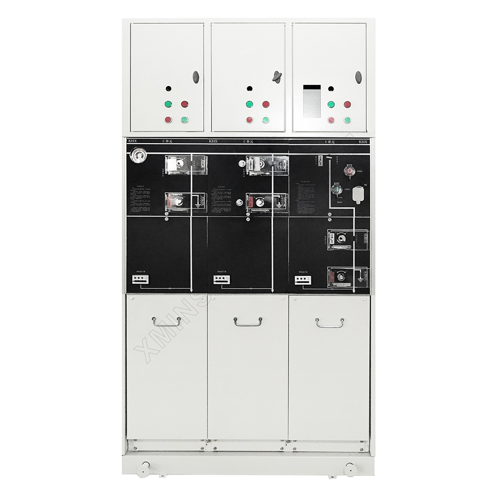
Switchgear Structure

- 熔断器室. Fuse room.
- 电容性电压指示器. Capacitive voltage indicator.
- 短路接地故障指示器(附件). Short circuit to ground fault indicator (accessory).
- 压力指示器. Pressure indicator.
- 具有序列号的标准. Standard with serial number.
- 模拟线路图. Analog circuit diagram.
- 熔断器熔断指示器. Blown fuse indicator.
- 面板上的挂锁装置. Padlock mechanism on panel.
- 电缆室. Cable chamber.
- RTU安装室. RTU installation room.
- 钥匙锁(附件). Key lock (accessory).
- 断路器操作孔. Circuit breaker operating hole.
- 负荷开关操作孔. Load switch operating hole.
- 接地开关操作孔. Grounding switch operation hole.
- 隔离开关操作孔. Isolating switch operating hole.
- 分闸按钮. Opening button.
- 合闸按钮. Closing button.
Design Notes
- Technical Description
The 24kV series inflatable switch cabinet is installed on a galvanized sheet frame, and the switch unit is in an SF6 air box. The air box is made of corrosion-resistant and non-magnetic 3mm thick stainless steel plate.
The SF6 air box is a “sealed pressure system” that can operate for 20 years under normal working conditions. The pressure of SF6 gas during normal operation is 0.15~0.4bar. The air box is equipped with a pressure release device to ensure that the gas can be released from the bottom or rear when the pressure is too high.
- Switch Unit
The load switch adopts a coaxial rotating double breakpoint method, and cooperates with the sliding plate through the same operating hole for kinetic operation. Therefore, the switch can only be in one of the three states of “closing, opening, and grounding” at any time, completely avoiding errors. operate.
- Operating Mechanism
The operating mechanism of the switch is installed on the front outside the air box. It is treated with special technology to prevent corrosion, facilitate manual operation and maintenance, and can easily realize electric operation.
Usage Environment and Conditions
- The ambient air temperature does not exceed 40℃, and the average value measured within 24 hours does not exceed 35℃, and the minimum ambient air temperature is -40℃;
Altitude ≤2000m.
- Humidity: Relative humidity: the daily average does not exceed 95%, and the monthly average does not exceed 90%.
- Water vapor pressure: the daily average value does not exceed 2.2KPA, and the monthly average value does not exceed 1.8KPA.
- Earthquake intensity: no more than 8 degrees, horizontal acceleration ≤ 0.4g, vertical acceleration ≤ 0.2g.
- Special conditions of use: When the actual use conditions exceed the normal use conditions, the user and the manufacturer shall negotiate.
Installation Dimension Drawing

Foundation Diagram
Standard Unit.

24kV Metering Cabinet.


GIS Switchgear Operating Mechanism
The operating mechanism room is located in the upper part of the GIS cabinet. The mechanism rollers are closely matched with the switch operating panel. The bolt fixing mechanism is divided into single spring (incoming line mechanism) and double spring (outgoing line mechanism) to form the ring network loop and transformer loop respectively. The switches and springs are all disc springs, which have the characteristics of high assembly precision, small operating force, long life and high stability.

Each module of the 24kV switchgear has the following configuration:
Capacitive voltage indicator for incoming bushings;
Each air chamber is equipped with a pressure gauge to monitor the density of SF6;
Lifting lugs for lifting;
Operating handle.
Optional
Electric operating mechanism;
Cable short circuit and ground fault indicators;
Current transformers and meters;
Remote monitoring and ground fault indicator.

Remote Control and Monitoring Unit
24kV gas insulated type with integrated remote control, telemetry and telecommunication automation module realizes the intelligent application of ring network switchgear. The integrated automation of distribution system can be realized by connecting each unit with the dispatching center of higher level by means of communication. Distribution automation enables dispatchers to know the operation of the whole distribution network without leaving home, to locate faults quickly, to isolate faults automatically or artificially and to reconstruct the network, thus greatly shortening the area and time of power outage and reducing the losses caused by faults. In addition, load monitoring and allocation can be carried out conveniently, which is conducive to the rational use of the network.
The distribution automation system matches the switch cabinet. The system is designed as an open system, which includes two parts: station-based module and automatic terminal module. The automation terminal is a distributed modular design with high reliability. At the same time, its compact shape is easy to install in the compact switchgear.
Optional configuration and features:
16 switching inputs (single remote signal), isolation voltage 1500VDC Eight analog inputs (telemetry), including four currents (AC5A) Four Voltages (1*24VDC.3*100VAC/220VAC).
6 switching output (remote control, can be used for up to three switching combined) C type dry contact, 250VAC8A/30VDC8A, One RS485 communication port is used for remote communication, up to 1200m.
Selection function:
Calculating Functions of Feeder P, Q, kwh, Karh, F, etc. Current protection function, which can act on switching output or communication output。

Inlet/Outlet Line Protection
Transformers or lines are protected by vacuum switches/vacuum circuit breakers with protective relays and current transformers. When vacuum switch debt air circuit breaker is selected as protection, standard relay is SPAJ140 C or other domestic comprehensive protection relay.
SPAJ140 C Over current/Short Circuit/Grounding Protection Relay Voltage range: DC (18-265V) or AC (80-265V) ASG type protective CT:secondary current 5A Digital display setting current measurements and recorded fault data Setting Value Panel Button or Computer Settings Passive signal nodes can be protected by each segment Continuous Self-Checking and Alarm Output of Internal Faults (Software and Hardware).
Low constant overflow section I >
Fixed-time action current 0.5-5.0 In action time 0.05-300s reverse-time action current 0.5-2.5 InlDMT reverse-time action mode.
High constant overflow section 1>
Action current 0.5-40 In action time0.04-300s.
Low fixed value zero sequence flow passage Lo >
Fixed-time action current 0.1-0.8ln action time 0.05-300s.
Inverse-time action current 0.1-0.8in IDMT reverse-time action mode.
lo > in high constant zero sequence flow passage.
Action current 0.1-10 In action time0.05-300s.

Transformer/Line Protection: Our pneumatic transformer provides two types of transformer protection: load switch fuse combination and circuit breaker with relay protection.
Fuse Combination Module Using Load Switch: Transformer protection is a combination of current limiting high voltage fuse and load switch. The fuse chamber will be installed behind a separate locking housing located in the front of the unit. The load switch uses a spring energy storage mechanism, which can be triggered by a fuse pin.
In order to facilitate the replacement of the fuse, the end cap of the fuse chamber can be removed by using an operating handle. The front-end tripping mechanism of the fuse ensures the waterproof performance of the whole system.

Program Description
Scheme1: SA+CCF+.
Bus is equipped with lightning arrester and extended. Note: The number of switching units is not less than 3.

Scheme 2: CCF+.
Install arrester and extend it.

Scheme 3: CCFFF=CF.
The maximum number of units in a group is 6. Extended bus connections are required when more than 6 units are in use.

Scheme 4: W=M=FFF.
High Pressure Side Calculation.

Scheme 5: PT = FF =FCSLCF =FF=PT.
Single Bus Segmented Band Bus PT.


①SF6气压表SF6 air pressure gauge.
②带电显示器Live display.
③合闸、分闸位置指示Closing and opening position indication.
④接地位置指示Earthing position indication.
⑤负荷开关操作孔Load break switch operating hole.
⑥接地开关操作孔Earthing operating hole.
⑦开关操作位置选择滑板Switch operating position selection slide.
Product Schematic Diagram

Switchgear Enclosures

Auxiliary Contact: All load switches and circuit breakers can be equipped with 2NO+2NC indicating switch position. A parallel release coil (AC or DC) can be installed on a transformer switch/circuit breaker. The low voltage control unit is located behind the front panel.
Voltage Indication: Capacitive voltage indicator shows whether the bushing is charged and the socket on it can be used for phase checking.
Short Circuit/Grounding Fault Indicator: In order to facilitate fault location, the cable switch module can be equipped with short circuit/ground fault indicator for simple fault detection.
Electric Operation: Manual operation mechanism of cable switching unit and transformer unit is a standard scheme. Electric operation mechanism can also be installed.Cable switches, vacuum circuit breakers and grounding switches are operated by a mechanism located behind the front panel. For all switches and circuit breakers, they can be operated by operating handles (standard configuration), or can be equipped with motor operating mechanisms (accessories). However, the grounding switch can only be operated manually and is equipped with a mechanism capable of closing the fault current. Electric operation mechanism can be easily implemented in stages.

Cable Connection: Our gas insulated cabinet is equipped with standard bushing. All bushings are of the same height from the ground and are protected by cable chamber covers. The cover plate can be interlocked with the grounding switch, and special double cable chamber cover plate can also be used for double cable access.

Pressure Indicator: Usually equipped with pressure indicator, which is in the form of pressure gauge. In addition, electrical contacts can be equipped to indicate pressure reduction.
Arc Extinguishing Device: Arc extinguishers can be installed in all 24 gas insulated ring network units. When the internal arcing occurs, the arc extinguisher automatically closes on the incoming bushing. 24kV GIS switch and all cable modules including D, De and V modules can be equipped with an arc extinguisher. They must order with the unit without changing it.
The action of the arc extinguisher can be indicated by this method to connect the electrical contacts in the SF。 cabinet to the terminal behind the front panel.

External Busbar: switchgear can be equipped with external busbar.

Base: Gas insulated switchgear can be installed on a separate base. The design of the base has reserved cable entrance at both ends and behind. Two different heights are 272 mm and450 mm respectively.

Secondary line chamber/low pressure chamber: switchgear can be equipped with secondary cabinet or low voltage box on the top of the switchgear. The secondary cabinet is used to install ammeter (with or without switch) and live locking control unit. The low-voltage box is used to install relays such as SPAJ140 C, ammeter (with or without switch) and live locking control unit.

Lightning Arrester: Zinc oxide arrester can be installed in the cable of our switchgear cabinet, and zinc oxide arrester can also be installed in the bus or MP cabinet of our switch cabinet.

◆Special Customization
The above parameters are typical data; if the existing styles do not meet your specific demands, please contact us for a custom design.We have significant personalized customization development and production skills, allowing us to provide tailored solutions to customers all over the world.


